Here is a quick method to create SOLIDWORKS Sketch Normal to Curve without having to create a plane first, and then sketch on that plane.

First, select the curve or edge, as shown in the sheet metal example below, then click Sketch from either the Insert menu or the Sketch CommandManager.

This will start a sketch on a newly created plane that is normal to the curve, located at the nearest endpoint on the curve.

Upon exiting the sketch, you will notice that a new plane has been created and is located in the FeatureManager design tree.


Article by Rod Mackay

How import and export Hole Wizard data with Excel files in the Configuration tool with SOLIDWORKS.

Formerly this could only be done with SOLIDWORKS Toolbox Hardware. This is an easier way to add custom Hole Wizard sizes within the Excel interface.

Do one of the following:


  • In SOLIDWORKS, click Tools > Options > System Options > Hole Wizard/Toolbox > Configure.
  • From the Windows Start menu, click All Programs > SOLIDWORKS 2018 > SOLIDWORKS Tools > Toolbox Settings 2018> Configure.

SOLIDWORKS 2018 Import and Export Hole Wizard Data

An Excel file can be exported first to obtain the proper setup and existing sizes. This Excel file has 3 tabs at the bottom, corresponding to the Standard Properties of each Hole Wizard type:

Sizes

Thread Data (except for Straight Holes)

Screw Clearances (except for Tapped Holes)


Once you have customized the exported Excel file, save as a separate filename (so you have a copy of the original Excel setup) and then use Import Hole Data Tables.

SW-Errors-SOLIDWORKS-2018 Hole-Wizard-Export

SOLIDWORKS 2018 Hole Wizard Export – Sizes

SW-Errors-Hole-Wizard-Export–Thread Data

SOLIDWORKS 2018 Hole Wizard Export – Thread Data

SW-Errors-SOLIDWORKS-2018-Hole-Wizard-Export – Screw Clearances

SOLIDWORKS 2018 Hole Wizard Export – Screw Clearances

For Thread Data, be sure to have a matching “full-size” to the “size” in the Sizes tab.


By Scott Durksen

The ‘Toolbox is currently in use’ issue can occur if users are accessing Toolbox during a SOLIDWORKS installation, but it can also be the result of a file that normally gets deleted, not being deleted. 

The file is called SWBrowser.ldb and by default resides in the lang\english sub-folder of your SolidWorks Data folder.
Deleting the file SWBrowser.ldb

Toolbox SWBrowser.ldb Location


Deleting the file SWBrowser.ldb will allow the installation to proceed.


Article by Joe Medeiros

Have you ever wondered how SOLIDWORKS knows which part belongs to Toolbox and which one does not? 

Or did you ever want to take a Toolbox part and modify it to create a custom part?
When you save a SOLIDWORKS Toolbox part as a copy, it will still have a Toolbox flag icon? Indicating it’s still going to be treated as a Toolbox file in file references. You can remove this flag very easily to have the part be treated as a normal SOLIDWORKS part by running a utility that is installed with SOLIDWORKS.

Important: only set this on Toolbox parts that you have created copies of, and not on the out of the box Toolbox parts, as this can severely affect the way Toolbox files are managed in the software.

Browse into the SOLIDWORKS installation folder which is usually located at:
C:\Program Files\SOLIDWORKS Corp\SOLIDWORKS
Then, inside the Toolbox\Data Utilities folder you’ll see a program called “sldsetdocprop.exe“
.
Sw-errors-Solidworks-path

Toolbox Data Utilities Location

Run that program and you’ll be able to add any files that have a Toolbox flag, simply:
Add the files,
Set the “Property State” to “No“,
And click “Update Status”.

Solidworks-set-document-property.jpg

Set Document Property

This will remove the Toolbox flag and the part will now behave like a normal SOLIDWORKS part.

Article by Saeed Mojarad 

A Toolbox custom property can be linked to SolidWorks materials library using the list option. 

The material selected in the Toolbox configurator gets applied to the Toolbox part and the custom property can be displayed in the BOM. Only one Toolbox property can be linked to SolidWorks materials library.

SW-errors-Material in a Toolbox part

Solidworks material in a Toolbox part

Toolbox material in BOM

Custom properties are added to Toolbox parts using Toolbox Settings. This dialog is accessed from Tools > Options > Hole Wizard/Toolbox > Configure or from the Start menu (eg. Start > SolidWorks 2015 > SolidWorks Tools > Toolbox Settings 2015).
Go to Toolbox Settings > Customize Hardware (step 2) and select the standard, category or type that require new property
Select the icon for ‘Add new Custom Property’ to bring up the Custom Property Definition dialog
Enter the property name (eg. Material)
Select the ‘List’ button and note that the option ‘Link to SW material’ appears
Select the ‘List’ option and click ‘Select’ to bring up the list of SolidWorks materials available
Select SolidWorks material and enter the name for BOM display
Repeat the previous step until the list of Toolbox materials is complete
Confirm OK and save Toolbox changes

Linking Toolbox property to SOLIDWORKS materials


Linking Toolbox property to SOLIDWORKS materials
Any materials added to the list will appear in the Toolbox configurator when the part is created or edited.

Toolbox property linked to SOLIDWORKS materials


Toolbox property linked to SOLIDWORKS materials.


Article by Sanja Srzic

Have a macro that you’d like to run on all models in a directory while out of the office?

Solidworks Task Scheduler Custom Task
Create Custom Task

Enter the Task Scheduler. Located in the SolidWorks Tools directory in your Start Menu, this program allows you to schedule batch operation tasks like updating the versions of your files, converting your models to DXF, updating custom properties, and so on. Those with SolidWorks Professional or Premium have the “Run Custom Task” option, which allows you to schedule the execution of a macro as well as specify its parameters.


As an example, let’s say that each night at 12:00 AM you want to open up every part in a directory and change the display setting to “shaded without edges”. Here are the steps you would follow:


1. Write a macro that opens up every part in a specified directory and changes the display the setting. In the code below you can see that the current specified directory is “C:\custom_task\”.

Dim swApp As SldWorks.SldWorks
Dim swModel As SldWorks.ModelDoc2
Const strFolderPath As String = "C:\custom_task\"
Dim strFileName As String
Sub main()
Set swApp = Application.SldWorks
strFileName = Dir(strFolderPath & "*.SLDPRT")
While strFileName <> ""
Set swModel = swApp.OpenDoc6(strFolderPath & strFileName, _
swDocPART, 1, Empty, Empty, Empty)
swModel.ViewDisplayShaded
swModel.Save3 1, Empty, Empty
swApp.QuitDoc swModel.GetTitle
strFileName = Dir
Wend
swApp.ExitApp
End Sub

2. Copy the code from the VB editor to Notepad and change the strFolderPath value to $$$FOLDER_PATH$$$. Your variable declaration for strFolderPath should now look like this:


Const strFolderPath As String = $$$FOLDER_PATH$$$

3. Save the text file as a .swb file.
4. Open Task Scheduler
5. Choose Run Custom Task
6. Click the Browse button next to Macro File Path and locate the .swb you just created
7. In the task parameters section, you should now see a parameter called FOLDER_PATH. Click in the Parameter String cell on the right and enter the directory that contains the files you want to convert to shaded without edges
8. After specifying the running mode, start time, and start date, click Finish and your task should be added to the queue. If you left the start time and date at their initial values then the task should start running immediately.
Example Solidworks macro
Example macro
Some additional comments and notes about using the Task Scheduler with macros:

  • You can also run regular .swp files using the Task Scheduler. With these files, however, you cannot specify parameters. The macro will simply run “as is”. To be able to specify parameters you have to use an .swb file.
  • Optionally, you can simply change the variables in the .swp file to $$$$$$, save the .swp file, and then rename the extension to .swp.
  • You can control string an numeric parameters using the Task Scheduler. Use $$$$$$ for string values and ###### for numeric values.
  • If you do not use ISldWorks::ExitApp at the end of your macro, the SolidWorks application will not close after the task is finished running. Consequently, the task will not be marked as Complete within the Task Scheduler.
  • You do not need to have the Task Scheduler open for the scheduled task to run.
  • Any dialog boxes created by macros run by the Task Scheduler will automatically be closed. This is done to prevent dialog boxes from stalling the execution of the tasks.


Article by Keith

How do you run your macros right now?

 Tools–>Macro–>Run? By clicking Run on the macro toolbar? If macros are even a small part of your workflow, you can do much better. In this post, I want to increase your versatility by showing you four ways you can run a macro without having to use the Run button.

1. Using custom toolbar and keyboard shotcuts

Many of you may know of this option already, but it is still worth mentioning. You can create custom toolbar shortcuts for any macro by going to Tools–>Customize, Commands tab, choosing the Macro category from the list on the left, and then dragging the New Macro Button icon onto a toolbar of your choose.
Solidworks-Add-Macro-Button
Add Macro Button
As soon as you release the mouse button, you should get a dialog prompting you for the macro location (which you can browse for), the button tooltip, and the method. Specifying the correct method is very important since this is the first method that will be run when the macro is executed.
Solidworks-Customize-Macro-Button
Customize Macro Button
If you want to take it step further, while you’re still in the Customize dialog box, go to the Keyboard tab, search for your new macro button, and add a keyboard shortcut.

2. When Solidworks starts

This option is invaluable for event-based macros that run code when a certain event fires, because it is ensures that you never forget to turn on the macro when SolidWorks starts. (To see some great examples of event-based macros, check out our Macro Library and look under the Notifications section.) After you create a shortcut directly from your executable, go into the shortcut properties and modify the target using the following syntax:

“<path to SolidWorks executable>” /m “<path to macro>”
As an example, if your SolidWorks executable is in the default file location on Windows 7 x64 and your macro, called “macro.swp”, is on C:\, your target would look like this:

“C:\Program Files\SolidWorks 2012\SolidWorks\” /m “C:\macro.swp”
Solidworks-Shortcut-property
Solidworks Shortcut property

3. From another macro


Yes, it is possible to “chain” macros to together using ISldWorks::RunMacro2. In this method you’ll find arguments that allow you to specify the path to the macro you wish to run and also the initial method that you want to run. This is a great option when you want to keep tasks separate in your macro workflow or quickly swap out tasks. For example, your main macro might have a form that allows a user to specify a macro to run before or after your main task is accomplished.
To see a very simple example of ISldWorks::RunMacro2, check out “Run a macro from another macro” in the Macro Library.

4. From the Design Binder

Many SolidWorks users do not know what the Design Binder is, let alone that you can run macros from it. The Design Binder is essentially a backpack for your SolidWorks model that allows you to attach relevant documents. This could include a word document, a spreadsheet, and, yes, even a macro. Consequently if you have written a macro specific to a document and need to make sure that the two stay together, attaching it to the Design Binder is a great option. Then if you write another macro that needs to run the macro attached to the Design Binder, you simply call ISldWorks::RunAttachedMacro. Much like ISldWorks::RunMacro2, you need to specify the sub procedure you want to run initially.
Solidworks-Design-Binder
Design Binder
Do you know of any other useful ways to run a macro? Please share below.

5. From the Task Scheduler

Have a macro that you’d like to run on all models in a directory while out of the office? Enter the Task Scheduler. Located in the SolidWorks Tools directory in your Start Menu, this program allows you to schedule batch operation tasks like updating the versions of your files, converting your models to DXF, updating custom properties, and so on. Those with SolidWorks Professional or Premium have the “Run Custom Task” option, which allows you to schedule the execution of a macro as well as specify its parameters. Learn more about using macros with the Task Scheduler here.

6. From a macro Feature

Macro features are custom SolidWorks features defined by the SolidWorks API. They reside in the feature-tree and can be added, edited, and deleted like any other feature. The bulk of the code defining a macro feature gets run when a document rebuilds, so during this time you can have the macro perform any task that doesn’t cause a rebuild. You can learn more about macro features here. Note, however, that macro features are ideally used for actually modifying geometry. If you simply want to run some code every rebuild, I’d encourage you to use equation-triggered macros instead, which are described in the next section.
Solidworks-Macro-Feature
Macro Feature

 7. From an equation

Few know that you can insert VBA code in an equation so that it gets run every time the equation is recalculated (which is every rebuild). Combine this trick with ISldWorks::RunAttachedMacro and ISldWorks::RunMacro2, which I described earlier in this post, and you have a pretty nifty technique for embedding and running macros while a part or assembly is open. Plus, the macro can travel with the document if you desire. These types of macros, which I call equation-triggered macros, are explained in great detail here. ETMs are usually the most effective way to run a macro without involving the end user.


Article by Keith

The Problem:

A question we often get on the support line is in regards to this error message:

Hole Wizard Database File Error Message

SolidWorks Hole Wizard Database File Error Message

It reads: “Error: The database file ‘C:\SolidWorks Data\lang\english\swbrowser.mdb’ is not the expected version (16.02)”
The file path and the number shown may vary.

The Cause:

Basically what is happening is that you have multiple versions of SolidWorks installed on your computer and SolidWorks is getting confused. It is also possible that you had an earlier version of SolidWorks installed on your computer and it did not completely uninstall. Having multiple versions of SolidWorks installed is a supported practice, but there are some things to keep in mind. I refer you to this blog article about installing multiple versions of SolidWorks, but at this point, you’ve probably already installed SolidWorks and don’t have time to completely uninstall all versions of SolidWorks and just want the hole wizard to work.
Luckily, it is an easy fix.

The Solution:

Accessing the Hole Wizard Settings

Accessing the Hole Wizard Settings


  • You need only go to Tools > Options, then under the System Options tab, select Hole Wizard/Toolbox from the list on the left. You will see the error message again, but don’t worry – this should be the last time you see it.
  • Click on the … button to browse to the correct path. If you’ve named your folders correctly for multiple installs as described in the aforementioned blog article, this will be easy to figure out. If not, you will need to figure out which SolidWorks Data folder matches the version of SolidWorks you are using. There will likely be multiple folders, called “SolidWorks Data (2)”, “SolidWorks Data (3)” and so on.
  • Regardless of what the folders are called, you need only pick the correct folder and click OK. If you guess wrong, you will see the error message again and you can simply try again.
  • If you try all the folders and none of them work, you would be well advised to contact your VAR for further technical assistance.


Article by Jim Peltier

Sometimes when you launch SOLIDWORKS and try to load SOLIDWORKS Toolbox Library or Utilities add-in, SOLIDWORKS delivers a message stating “You appear to have experienced problems the last time you loaded the SOLIDWORKS Toolbox add-in”.

SOLIDWORKS Message

  • If you pick yes, continue to load Toolbox, SOLIDWORKS stops responding?! 
  • However, if you pick No, disabling Toolbox, everything seems to work fine.
This issue is only experienced in SOLIDWORKS 2017. 

This issue has been fixed in SOLIDWORKS 2017 SP4 which is scheduled to be released for the week of July 24th, 2017.


To avoid the issue in previous service packs of SOLIDWORKS 2017 you should delete the ‘tb_default.sldedb’ from ‘<C:\Users\<user>\AppData\Roaming\SOLIDWORKS\SOLIDWORKS 2017\Toolbox\data’.


Then re-launch SOLIDWORKS, you should have no issues adding the Toolbox Library or Utilities add-in.


Article by Vipanjot Kaur - CSWP

Have you ever seen these messages before launching SOLIDWORKS? There is no SolidWorks database. Full functionality is not available.

SW-errors SolidWorks Database is missing error message
SolidWorks Database is missing error message
There is no error message in the SolidWorks database Or what about the SOLIDWORKS error message? Failed to initialize library of tools
Solidworks Errors  Message
Failed to initialize Error Message
Not to worry! This means that the Hole Wizard / Toolbox function could not find the important database file SWBrowser.mdb.

Solving the problem of the lack of a SOLIDWORKS database

The fix is ​​simple. Open the SOLIDWORKS settings in the Tools> Options menu and select the Hole Wizard / Toolbar on the System Settings tab.
Change Solidworksdata path
SolidWorks Toolbox options

The path specified in the "Hole Wizard and Tools" folder must contain the \ lang \ english folder, and the English folder must have the SWBrowser.mdb file. When you install SolidWorks by default, you must set the parameters that point to C: \ SolidWorks Data, and the MDB file will be located in the C: \ SolidWorks Data \ lang \ english \ SWBrowser.mdb folder.
Therefore, if you have error messages, go to the folder specified in the toolbar options, and see if there is a file \ lang \ english \ SWBrowser.mdb. And make sure that you have full permissions to get there! If necessary, change the path to the Toolbox above by clicking the "..." button.

If you can not find the SWBrowser.mdb file or if you still have problems, try repairing SOLIDWORKS


Article by Scott Durksen, CSWE

Windows 7, 8.1 and 10, include a feature called User Account Controls (UAC) which prevents access to the Windows registry files. However SOLIDWORKS requires access to the Windows registry during installation and even when running.


Issues when installing SOLIDWORKS


During installation, many items are written to the registry. With UAC enabled, these items can become corrupt or blocked completely as it is attempting to prevent the installation. It is recommended to disable the UAC, along with any antivirus/antispyware software, before installing SOLIDWORKS. If SOLIDWORKS was installed with the User Account Controls and Antivirus enabled, you may experience issues with your software.

Issues when running SOLIDWORKS


Once SOLIDWORKS is installed, the UAC can still cause errors when running. Some known issues are connecting to the SolidNetwork License server, loading the Toolbox, using equations & macros, and running Simulations ). We recommend keeping UAC disabled for machines running SOLIDWORKS.


Windows UAC setting SOLIDWORKS


In all Windows versions, the UAC can be found under Windows Control Panel > User Accounts > Change User Account Control settings. Below are shortcuts that can be used to access the UAC:


To disable UAC in Windows 7:


Go to Start > type UAC in the search box

Slide the bar down the bottom for “Never notify”
SW-errors User Account Control Settings
User Account Control Settings
Restart your computer

To disable UAC in Windows 8.1:


Press the Windows key on your keyboard to get to the Start screen
Type “uac” to start a search
Select “Settings” under the search box and press Enter

SW-Errors-UAC access
UAC access
Slide the bar to “Never notify
Restart your computer

SW-errors User Account Control Settings
User Account Control Settings

To disable UAC in Windows 10:


Press the Windows key on your keyboard to get to the Start screen
Type “uac s” to start a search
Select “Change User Account Control settings” in the results

SW-errors Windows 10 UAC
Windows 10 UAC

Slide the bar to “Never notify
Restart your computer

SW-errors User Account Control Settings
User Account Control Settings


Article by Scott Durksen, CSWE

Much like when SOLIDWORKS made your first sketch dimension auto scale your whole part back in 2014, with the release of SOLIDWORKS 2018, they have added another feature that users have asked for which makes modeling your designs easier even if it seems like a minor update at first glance.

If you change your mind on the choice of hole in the SOLIDWORKS 2018 Hole Wizard tool, you no longer need to remember and re-input your hole specifications!


Whether it is a design change late in your design process, or a change when you are first defining the part, it will be made easier by not needing to re-define your hole wizard settings every time a change is made.
This feature is configurable, so if the previous method of each hole type having a default setting is preferred, the setting can be changed in the system options under ‘hole wizard / tool box’ settings.

Solidworks errors Updated required to counter bored holes in slats
Updated required to counter bored holes in slats

Lets see it in action
To take a quick look at the change to the Hole Wizard, we will use this shelf which currently has a counter bored hole to receive a pan head machine screw for mounting the slats. A design review has revealed that consumers MUCH prefer a counter sunk flat head screw on their shelf slats, and so you have been tasked with switching the configuration to use a counter sunk fastener.While this is an over simplification, it would still require modifying the hole definition, and when changed to a counter sunk style, the current hole settings would previously be lost.
With SOLIDWORKS 2018, the settings used for the counter bored hole will be maintained when switched to a counter sunk hole.

SOLIDWORKS 2018 retains hole specifications when selecting a new hole type!

Updated counter sunk holes in slats

This feature is configurable, so if the previous method of each hole type having a default setting is preferred, the setting can be changed in the system options under ‘hole wizard / tool box’ settings.


Article by Bryan Sprange, CSWE

SOLIDWORKS 2018 adds SOLIDWORKS Toolbox hexalobular fasteners, commonly known as Torx. 

The 6-point star shaped drive can be found in automobiles, power equipment, computers, electronicsm, etc . As the hexalobular profile has been standardized under ISO 10664, you can find these fasteners under the ISO standard in the Toolbox.
SOLIDWORKS 2018 Hexalobular (Torx) Hardware
Toolbox ISO Hexalobular Directory
SOLIDWORKS 2018 Toolbox ISO Hexalobular Directory

The hexalobular types included are:

ISO 14587 (2011) Hexalobular Socket Raised Countersunk (oval) Head Tapping Screws 

ISO 14581 (2013) Hexalobular Socket Countersunk Flat Head Screws 

ISO 14582 (2013) Hexalobular Socket Countersunk Head screws, High Head
SOLIDWORKS 2018 Toolbox Hexalobular Hardware Types

ISO 14584 (2011) Hexalobular Socket Raised Countersunk Head ScrewsJust like with any other Toolbox fastener, these can be customized to add sizes or properties.
SOLIDWORKS Toolbox Configuration


Article by Scott Durksen

Error Solidworks Toolbox:


  1. Failed to get writable document
  2. Unable to open read-only file
  3. Failed to  save Toolbox library: Access to the path is denied
  4. You appear to have experienced problems the last time you loaded the Solidworks Toolbox add-in

Failed to get writable document


In this case, you need to check the access rights to the Toolbox directory (by default C: \ Solidworks Data can be viewed in the Toolbox settings)
Solidworks Change Options
Solidworks Options
Change Solidworks Toolbox Location


To do this, right-click on the Toolbox-Properties - Security tab. Check that your account has write permissions.


Unable to open read-only file


With this error, you must tick the "Change the status of the read-only document to the record" in the Toolbox- "User Settings" configurator settings
Change Solidworks Toolbox location
Change the status of the read-only document to the record


Failed to  save Toolbox library: 

Access to the path is denied


In the third case, you need to check the write permission of the "ToolboxFiles.index" file, which is located in the Toolbox - \ Browser directory. This error may appear in SW2012 and higher versions. This is due to the fact that starting from Solidworks 2012 the toolbox does not depend on the SWBrowser.mdb database, but stores the structure in the "ToolboxFiles.index" file.
SOLIDWORKS Smart fasteners have their own page in the SOLIDWORKS Toolbox Settings: Step 5 – Configure Smart Fasteners. This is where washer size and fastener length are set and a default fastener is specified for the holes created without Hole Wizard.
Solidworks Smart Fasteners Options
Smart Fasteners Options

The option to change the default SOLIDWORKS Smart Fastener type for Hole Wizard holes can be found in the Step 1 – Hole Wizard of the Toolbox Settings. 
That is where each hole type gets a matching fastener from the Toolbox selection.
The Reassign button can be used to change the default fastener for the selected hole type.

Solidworks Reassign Default Smart Fasteners
Reassign Default Smart Fasteners


Article by Sanja Srzic

If you encounter problems with an installed SOLIDWORKS product
(e.g. SOLIDWORKS Premium, Simulation, PDM, Inspection, Electrical etc.), you can use the SOLIDWORKS Installation Manager to repair the installation.

 However, to repair an installation, your machine must have all the source files from the previous installation and any service packs that were applied, in the location where they were originally installed.
You can repair an individual installation. You cannot repair an administrative image; you must uninstall and then reinstall the administrative image

Repairing SOLIDWORKS installation


Here are the steps for repairing SOLIDWORKS:

Step 1. Make sure you have the SOLIDWORKS installation files. If you installed from the SOLIDWORKS DVD, place the DVD into the drive. 

 If you installed from a file set downloaded directly from solidworks.com, make sure the files are present in the SOLIDWORKS Downloads folder.

Step 2. If you are using Windows Vista or Windows 7, disable the User Account Control as directed in the article Avoid potential problems using SolidWorks with Windows Vista & 7


Step 3. Ensure that any antivirus and /or antispyware software services have been stopped. 

 This can be done by going to the Start menu and launching the Run dialog. Type in: services.msc then click Run. Find the antivirus and antispyware services in the list and select Stop.

Step 4. Go to the Control Panel and open Add/Remove Programs if using Windows XP, Programs & Features if using Windows Vista or Windows 7.

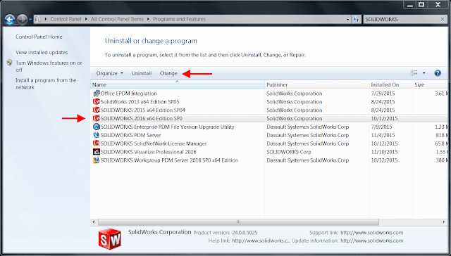
Step 5. Select the SOLIDWORKS installation from the list and click Change.

Windows Control Panel

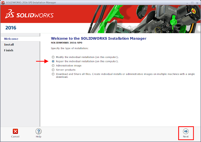
Step 6. Select the “Repair the individual installation” option and click Next.

Repair installation Manager

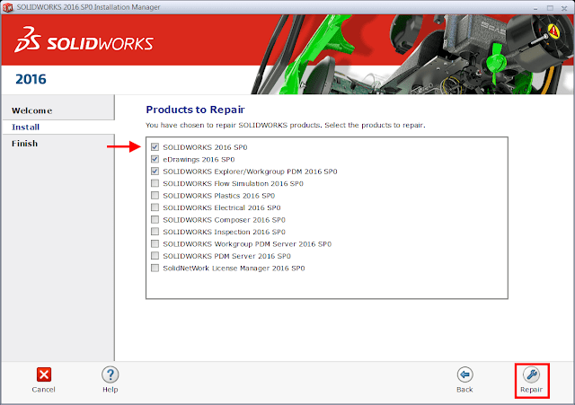
Step 7. On the Products to Repair screen, select the product to repair

Products to Repair
Products to Repair

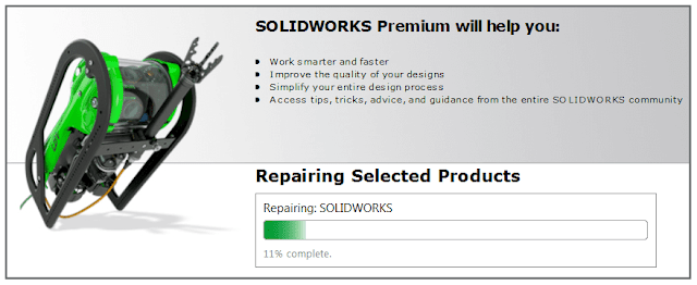
Once the repair is complete, launch SOLIDWORKS to test if the issue has been resolved.

Article by Andrew Lidstone 

Search This Blog

Избранное сообщение

How to quickly create a SOLIDWORKS Sketch Normal to Curve

Here is a quick method to create SOLIDWORKS Sketch Normal to Curve without having to create a plane first, and then sketch on that plane. F...

Popular posts