SOLIDWORKS Smart fasteners have their own page in the SOLIDWORKS Toolbox Settings: Step 5 – Configure Smart Fasteners. This is where washer size and fastener length are set and a default fastener is specified for the holes created without Hole Wizard.
Solidworks Smart Fasteners Options
Smart Fasteners Options

The option to change the default SOLIDWORKS Smart Fastener type for Hole Wizard holes can be found in the Step 1 – Hole Wizard of the Toolbox Settings. 
That is where each hole type gets a matching fastener from the Toolbox selection.
The Reassign button can be used to change the default fastener for the selected hole type.

Solidworks Reassign Default Smart Fasteners
Reassign Default Smart Fasteners


Article by Sanja Srzic

If you encounter problems with an installed SOLIDWORKS product
(e.g. SOLIDWORKS Premium, Simulation, PDM, Inspection, Electrical etc.), you can use the SOLIDWORKS Installation Manager to repair the installation.

 However, to repair an installation, your machine must have all the source files from the previous installation and any service packs that were applied, in the location where they were originally installed.
You can repair an individual installation. You cannot repair an administrative image; you must uninstall and then reinstall the administrative image

Repairing SOLIDWORKS installation


Here are the steps for repairing SOLIDWORKS:

Step 1. Make sure you have the SOLIDWORKS installation files. If you installed from the SOLIDWORKS DVD, place the DVD into the drive. 

 If you installed from a file set downloaded directly from solidworks.com, make sure the files are present in the SOLIDWORKS Downloads folder.

Step 2. If you are using Windows Vista or Windows 7, disable the User Account Control as directed in the article Avoid potential problems using SolidWorks with Windows Vista & 7


Step 3. Ensure that any antivirus and /or antispyware software services have been stopped. 

 This can be done by going to the Start menu and launching the Run dialog. Type in: services.msc then click Run. Find the antivirus and antispyware services in the list and select Stop.

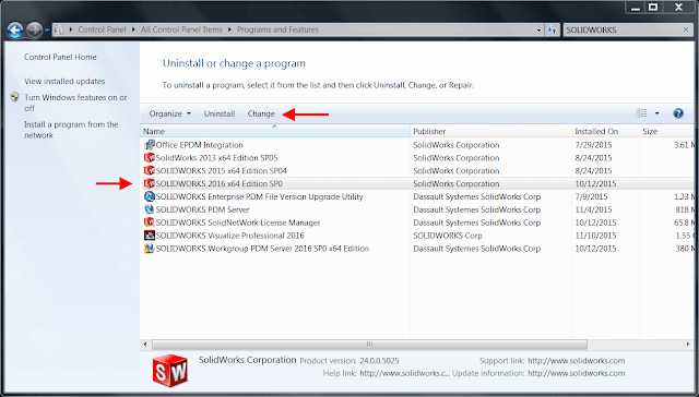
Step 4. Go to the Control Panel and open Add/Remove Programs if using Windows XP, Programs & Features if using Windows Vista or Windows 7.

Step 5. Select the SOLIDWORKS installation from the list and click Change.

Windows Control Panel

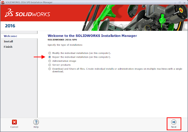
Step 6. Select the “Repair the individual installation” option and click Next.

Repair installation Manager

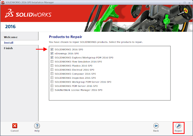
Step 7. On the Products to Repair screen, select the product to repair

Products to Repair
Products to Repair

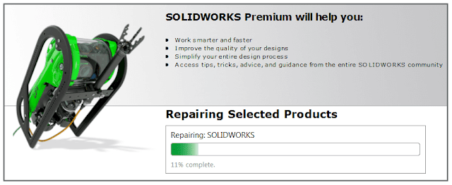
Once the repair is complete, launch SOLIDWORKS to test if the issue has been resolved.

Article by Andrew Lidstone 

All SOLIDWORKS Toolbox parts have an internal file flag that sets them apart from regular SOLIDWORKS parts. 

This flag enables SolidWorks to recognize them as standard parts and places a Toolbox icon beside them in the FeatureManager Design Tree. If you have created custom fasteners by copying files out of the Toolbox folders, these will still be recognized as a Toolbox part. As these are now stand-alone parts, SolidWorks will not need to search for the references within the Toolbox. Therefore you should remove the internal flag to avoid file reference conflicts.
When copies of Toolbox files are saved externally from Toolbox, it is sometimes necessary to remove the flag which identifies the file as originating from Toolbox. This article explains how to remove the Toolbox flag as well as how to determine what the current flag status is.

Custom sizes of the default fasteners can be added directly to the Toolbox, but sometimes it is necessary to take a copy of the Toolbox file in order to adjust the geometry. This may be done as an alternative to remodelling the fastener from scratch.
One of the issues that arise when copying fasteners from Toolbox is that the resultant part file maintains an internal flag. This internal flag can force SolidWorks to revert back to the original Toolbox item instead of the saved out part file when opening an assembly.

One solution to this problem is to deflag the Toolbox item. The result of this will be that the file is no longer recognised as having originated from the Toolbox and instead becomes a standard part file.


sldsetdocprop

sldsetdocprop

Window Set Document Property

Set Document Property


  • Browse to your SOLIDWORKS installation folder (by default C:\Program Files\SOLIDWORKS Corp\SOLIDWORKS\Toolbox\data utilities)
  • Add the individual part file or folder of files to be deflagged by selecting ‘add files’ or ‘add directories’
  • Set the property state to ‘No’
  • Click "Update Status"
    M5x.5 Tapped Hole

    These instructions are intended to create a New Standard for additional tapped holes or other features in the SolidWorks Hole Wizard and Toolbox. The following instructions show the steps for adding a Metric Fine Tapped Hole Standard. These Metric Fine Threads can be found on Festo Sensors for example.


    STEP 1

    On the Menu Bar (Standard Toolbar), Select Options → System Options → Hole Wizard/Toolbox → Configure…then the Toolbox Configure Window will appear. This method is shown below (a second method is from the SolidWorks Menu, Select Tools → Options → System Options → Hole Wizard/Toolbox → Configure… then the Toolbox Configure Window will appear).

    Solidworks Menu Bar Method
    Menu Bar (Standard Toolbar) Method

    STEP 2

    Solidworks Toolbox Setup Window
    Toolbox Setup Window
    Pick “1. Select your Hardware” from the Toolbox Setup Configure List.
    Toolbox Standards Window
    Toolbox Standards Window
    The Toolbox Standards Window will appear.
    STEP 3

    Uncheck/Turn Off Toolbox Standards Not Used
    Uncheck/Turn Off Toolbox Standards Not Used
    If this is your first time setting up the Hole Wizard/Toolbox. This is the point where you can Uncheck/Turn Off the Toolbox Standards that you Will Not Use. The reason for unchecking/turning off these Standards is so the Hole Wizard Drop-Down Menu will only contain the items that you use.
    Soliworks ANSI Metric Standard – American
    ANSI Metric Standard – American
    STEP 4
    Select the Standard that you wish to copy, for this example we will copying the American “ANSI Metric” Standard. Once selected the contents of the ANSI Metric Standard will appear. Also shown are the icons for Backup and Copy Standards.

    Solidworks Copy Standard Icon
    Copy Standard Icon

    Select the “Copy Standards” icon.
    STEP 5

    Solidworks Enter New Standard Name Box
    Enter New Standard Name Box

    The Enter New Standard Name Box will appear. Type in the New Name you wish to call this New Standard, we will be using the name “Metric Fine Threads”. You will notice that SolidWorks is creating a New Standard once the Green Check is selected.
    STEP 6

    Once the New Standard is created, you will now notice it on your main screen with the rest of your Standards. You will notice a Folder with a Red Cross; this is to Delete a Standard. If you want to remove a Standard in the future this is where you go to remove the Standard. Select the Metric Fine Thread located in the Left Panel.
    Solidworks - New Metric Fine Threads Standard Created
    New Metric Fine Threads Standard Created

    STEP 7
    Solidworks - Uncheck/Turn Off Items Not Required
    Uncheck/Turn Off Items Not Required
    The Contents of the Metric Fine Threads will appear. Uncheck/Turn Off everything that you Do Not want to show. You can always go back and Check/Turn On the items you want to show in the future. In this instruction, we will Uncheck/Turn Off everything except for the Hole Wizard Holes folder. Then Select the Hole Wizard Folder.
    Uncheck/Turn Off Straight Holes Folder
    STEP 8
    The contents will appear on the screen, Straight Holes and Tapped Holes folders. Uncheck/Turn Off the Straight Holes folder as we will be creating Tapped Holes. Select the Tapped Holes Folder.
    STEP 9
    Uncheck/Turn Off Bottoming Tapped Holes and Straight Pipe Tapped Holes Icons
    Uncheck/Turn Off Bottoming Tapped Holes and Straight Pipe Tapped Holes Icons

    The result will be 3 folders appearing on the screen, Bottoming Tapped Holes, Straight Pipe Tapped Holes, and Tapped Hole icons. Here we will Uncheck/Turn Off the Bottoming Tapped Holes and Straight Pipe Tapped Holes icons because we creating Tapped Holes.
    STEP 10
    Now Select Option #2 on the Top Toolbar on your screen, located to the right of Select Hardware.
    Select the Option #2 on the Top of Toolbar
    Select the Option #2 on the Top of Toolbar

    The Customize Hardware window will then appear.
    Solidworks - Select the Newly Created Standard, Metric Fine Threads
    Select the Newly Created Standard, Metric Fine Threads
    STEP 11
    Select the Newly Created Standard, Metric Fine Threads. The Hole Wizard Window will appear.
    Select the Hole Wizard Folder
    Select the Hole Wizard Folder
    STEP 12
    Select the Hole Wizard Holes Folder. The Tapped Hole Folder will appear now, Select the Tapped Hole Icon.
    Solidworks Enabled Column – Sizes
    Enabled Column – Sizes
    STEP 13
    Select the Tapped Hole Icon and the Sizes Window will appear. Now, Uncheck/Turn Off all the Coarse threads under the “Enabled” column.
    Add New Row Column – Sizes
    STEP 14
    Select the “Add New Row” Icon located to the Left of the Enabled Column. Now the Add New Row Window will appear.
    Solidworks - New Row Information Filled In – OK Button
    New Row Information Filled In – OK Button
    Type in the requested information, we add Size M5x.5, Pitch .5, and Diameter 5 for our M5x.5 Tapped Hole. Then Select the OK Button located at the Bottom Left Corner.
    The Toolbox Additional Information Window will appear, just Select Ok.

    Solidworks Toolbox Additional Information Required Window – OK Button
    Toolbox Additional Information Required Window – OK Button
    You will notice M5x.5 row added at the bottom of the screen.Solidworks - New Size Added – M5x.5

    Solidworks Thread Data Window
    Thread Data Window
    STEP 15
    Select “Thread Data” from the Left Side Panel.
    Select the “Add New Row” icon, located next Enabled.


    Add New Row Column – Thread Data
    Solidworks Add New Row Information Window – Thread Data
    Add New Row Information Window – Thread Data

    Now, the Add New Row Information Window will appear.

    STEP 16
    Fill in the requested information for a New Thread; we will be adding the information for an M5x.5 thread.
    Some of the Information Names are not clear thus, below is an explanation what they mean. In the bracket is the information used for our thread. The information used in this instruction can be found in the Machinery’s Handbook.
    Advance: Thread Pitch (.5)
    Thread Minor Thread: Minor Diameter of an External Thread (4.272)
    Thread Minor Thread Inside: Minor Diameter of an Internal Thread (4.599)
    Fullsize: Hole Callout Display (M5x.5)

    Select the OK button after all the information is filled in.

    Solidworks New Thread Data Added
    New Thread Data Added


    New Thread Data Information Filled Out
    New Thread Data Information Filled Out

    The New Thread Data is added and displayed in the bottom row.

    STEP 17
    The process is now completed. Select the “X” (Close) located in the Top Right Corner of the screen. There will be a “Toolbox – Save Changes?” Window appear after selection. Select “Yes” and the Hole Wizard/Toolbox Window will Close.
    Toolbox – Save Changes? Window
    Toolbox – Save Changes? Window

    STEP 18
    Now, we want to verify that the New M5x.5 Tapped Hole was correctly added to the Hole Wizard. We will create a new SolidWorks simple model to test our New Hole Wizard Tapped Hole.
    SolidWorks Test Model – Hole Wizard
    SolidWorks Test Model – Hole Wizard
    Then Select the Hole Wizard and Select Standard → Metric Fine Threads, Type → Tapped Holes, and Size → M5x.5. Select the Green Check Button.
    Hole Wizard Tapped Hole Information Selected
    Hole Wizard Tapped Hole Information Selected
    There you have it, an M5x.5 Tapped Hole!
    M5x.5 Tapped Hole
    M5x.5 Tapped Hole
    Now create a Drawing to check if the Tapped Hole Callout is correct.
    M5x.5 Tapped Hole Callout – Drawing
    M5x.5 Tapped Hole Callout – Drawing


    Congratulations, you have created a new Hole Wizard/Toolbox Standard.


    Article by Ralph Wright, CSWP

    Search This Blog

    Избранное сообщение

    How to quickly create a SOLIDWORKS Sketch Normal to Curve

    Here is a quick method to create SOLIDWORKS Sketch Normal to Curve without having to create a plane first, and then sketch on that plane. F...

    Popular posts